
- Wireless Sensor Network Components
- Mesh Networking
- Configuring Your NI WSN System
- Additional Information
Wireless Sensor Network Components
A wireless sensor network (WSN) is a wireless network consisting of spatially distributed autonomous devices that use sensors to monitor physical or environmental conditions. These autonomous devices, known as routers and end nodes, combine with a gateway to create a typical WSN system. The distributed measurement nodes communicate wirelessly to a central gateway, which acts as the network coordinator in charge of node authentication, message buffering, and bridging from the IEEE 802.15.4 wireless network to the wired Ethernet network. where you can collect, process, analyze, and present your measurement data. Figure 1 shows a typical NI Wireless Sensor Network, in which the three WSN measurement nodes are configured as end nodes.
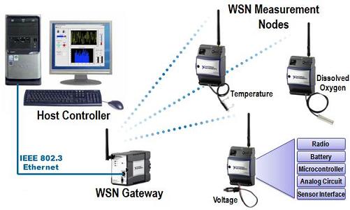
Figure 1. Basic WSN System with End Nodes, Ethernet Gateway, and Host PC
End Nodes vs. Routers
NI WSN measurement nodes can be configured to act as end nodes or routers using the NI Measurement & Automation Explorer (MAX) utility. In both configurations, the nodes can collect measurement data from sensors, control their DIO channels, or be programmed using LabVIEW WSN for more advanced capabilities. One trade-off to consider when configuring nodes is power consumption. To preserve battery power, an end node will reside in a low-power sleep mode most of the time (depending on its user-defined sample interval), waking up only to sample and transmit data, along with other housekeeping information. A router node, however, is always awake and can relay data from other nodes back to the gateway. This allows you to extend distance and reliability in your wireless sensor network. Because they are always transmitting data, router nodes are designed to use external power at all times to send, receive, and buffer messages to and from end nodes.
Mesh Networking
The gateways and nodes work together to form a mesh network. The gateway maintains a list of nodes (by serial number) that have been authorized for network access. When a node powers up, it scans for available networks, locates either a gateway or router, and attempts to join it. If the gateway has the node in its list, the node joins the network, downloads the latest configuration from the gateway, and begins its normal operation of acquiring measurement data and controlling DIO.
Since each node joins a network instead of a particular router or gateway, it can find a new path back to the gateway in the event that the signal is lost or blocked to its existing network route. In this way, the mesh network is inherently self-forming and self-healing. However, this may also cause network throughput to decrease, as there is no way to force a router or end node to join to a particular device in the network. Each time a node joins through a router, the overall throughput of that node is halved, due to the fact that the node must hop to get its messages back to the gateway. Figure 2 shows an example of one possible mesh configuration.
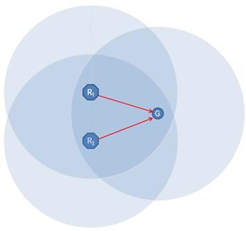
Figure 2. Mesh Configuration #1 with Router Nodes and Gateway
In this configuration, R1 (a router) and R2 (a router) both communicate directly with the gateway. Measurements taken by both devices can directly reach the gateway without having to hop through another node. However, the configuration above does not always mesh in the same way. Figure 3 shows another possible configuration for the same network.
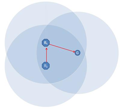
Figure 3. Mesh Configuration #2 with Router Nodes and Gateway
In this configuration, R1 can still communicate with the gateway, but R2 is now connected through R1. This means that all measurements taken by R2 must hop through R1 before making it back to the gateway. In addition, R1 is now not only responsible for sending its own measurement data, but also the R2 data. This configuration is considered a worst case 1-hop system, as R2 and R1 both have the possibility of meshing through a router that is connected to the gateway. NI recommends configuring your system for no more than three hops. Configuring multiple nodes as routers and placing them within close proximity introduces the possibility that your system could mesh inefficiently. Figure 4 shows how a system could mesh efficiently, yet also have the possibility of meshing inefficiently.
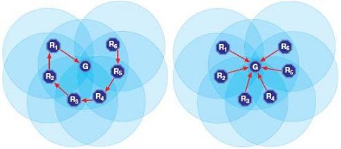
Figure 4. Same Topology - Two Ways to Mesh (Inefficient vs. Efficient)
This network can be improved with two separate techniques:
- Convert some routers to end nodes.
- Set up the network to prevent the routers from being in range of each other (spatially separated by distance, or introducing objects that increase radio interference such as buildings).
Another advantage of the mesh network is the ability to extend the distance of the end measurement from the wired gateway. By placing mesh routers throughout the space where you wish to acquire signals, you can expand the area and distance across which measurement data can be acquired and sent. In an outdoor environment with line of sight, a single communication hop can extend up to 300m. NI recommends no more than three hops from any device to the gateway, meaning you can extend your measurements up to 900m from the gateway.
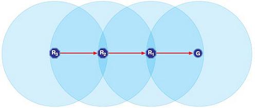
Figure 5. Using Router Nodes to Extend Network Distance
Configuring Your NI WSN System
As discussed in the Mesh Networking section, creating a reliable and efficient wireless sensor network requires an understanding of the physical environment the network will reside in, as well as an understanding of the expected meshing configuration. Additionally, the following consideration needs to be taken into account: parent devices (routers and gateways) can only have a maximum of eight end nodes connected to them at a given time. This means that to achieve the maximum density of 36 nodes per gateway, you must include router nodes in your topology.
If you wish to implement a star topology, in which no routers are utilized, you can only connect eight end nodes to your gateway, as seen in Figure 6.
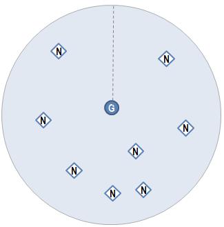
Figure 6. Maximum of Eight End Nodes in a Star Topology
To achieve the 36-node limit for WSN gateways, you can introduce router nodes into your system. Architecting your system will depend on your application, but the two most common 36-node mesh topologies can be seen below. In the topology illustrated by Figure 7, measurement points can be scattered among a large area that is only 2 hops from the gateway.
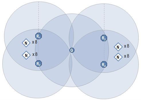
Figure 7. High-Density, Medium-Distance Mesh Topology Example
If distance is more important than measurement density in your application, you can architect a topology in which end nodes are three hops from the gateway, as seen in Figure 8.
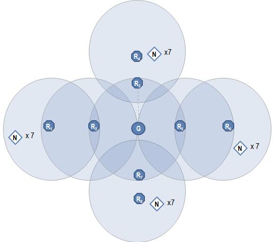
Figure 8. Medium-Density, High-Distance Mesh Topology Example
Keep in mind, however, that the 8:1 end node to parent ratio limit introduces a potential issue known as the stranded node problem. The stranded node problem exists when a node configured as an end node has the possibility of not being able to join a device. Figure 9 shows a network consisting of one gateway, two routers, and nine end nodes.
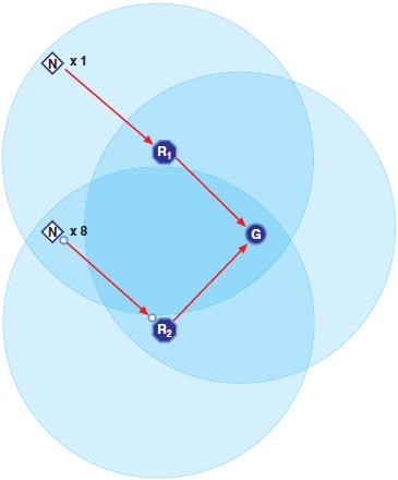
Figure 9. Mesh Topology Without Stranded Node
In this case, all nodes have properly meshed, and all nodes can communicate with the gateway. However, this network could potentially strand end nodes. Figure 10 shows another possible mesh of the same network.
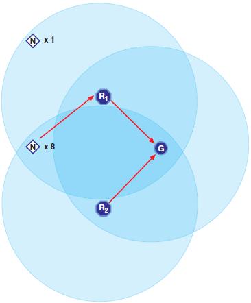
Figure 10. Mesh Topology With Stranded Node
In this mesh configuration, eight end nodes in range of both R1 and R2 join with R1. This leaves one end node stranded from the network. This can be corrected in the following two ways:
- Move the set of 8 end nodes to where they can only communicate with R2. This prevents them from
possibly joining R1. - Add an additional router that is in range of the single end node. This introduces the possibility of
creating additional hops in the network, but also guarantees coverage of all end nodes.
Additional Information
Wireless Sensor Networks are an exciting technology that can solve a variety of applications. To get started with NI Wireless Sensor Networks, purchase an NI WSN Starter Kit. Or to learn more, visit the NI WSN homepage.
No comments:
Post a Comment